Quanum Venture quadcopter part 4 – Adding FPV

FPV (First Point View) which stands for first-person-view is kind of video piloting, which is a method used to control a drone from the vehicle’s view point. And drone’s view point may can be displayed on a video screen so that remote controller can control her more easily even she is out of sight.
To achieve this I need to prepare these components:
1. CMOS camera
2. Wireless video transmitter (Mostly 5.8Ghz FM radio is used at RC world.)
3. Wirelss video receiver
4. Display screen or goggle

I prepared Eachine’s Cmos FPV set which CMOS camera, video TX and RX are bundled.
IMG_3808

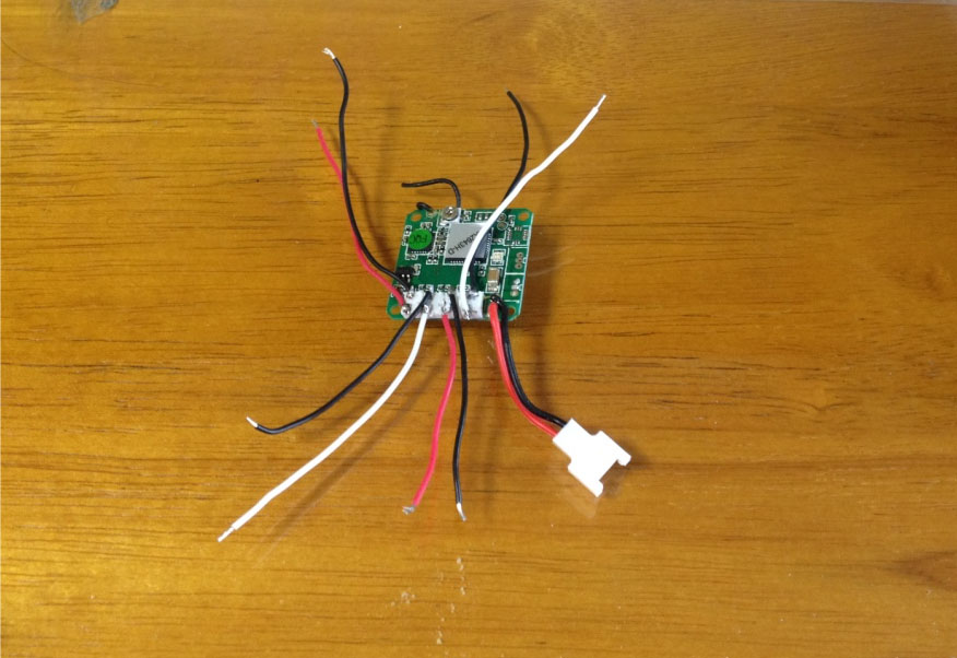
CMOS camera and video transmitter is air part. This TX has 200mw amplifier. So transmission range may will be 300~400m. Receiver is ground part which will be connected to video monitor to display the captured video from air part.
FPV parts

Before I put these into my quadcopter, I pre-tested these to prove this would work with no trouble. I connected the CMOS camera to the video TX, video RX to DVD displayer and fed 11.1v power at both video TX&RX, and captured video. Theses worked very nicely as I expected.
IMG_3810

When I measured wire length before put air parts into the my quadcopter, these wires are needed to be extended.
IMG_3867

I placed the Video TX at the tail and Camera at the head.
camera_video TX

When I tested video output after done the assembly, it worked very good.
IMG_3868


Quanum Venture quadcopter part 3 – The first flight testing

I went to airfield at Han river near my house for testing flight. I feded 11.1v 4200mah power to Quanum Venture and ready to lift her up.  It was very smooth and stable, but I needed to tune the yaw rate.
IMG_3796

Arducopter 3.2 firmware supported Autotune option, but it didn’t work properly. Needed to check this later. Overall flight time was more than 10 minutes with 4200mah capacity. Think need to buy new extra batteries.
IMG_3799

Here is the video link of the first testing flight. Thank you for my son to took this great video :

Quanum venture quadcopter part 2 – Parameters setting and making RTF

When I meet the Mission Planner and APM flight controller for the first time at last year. I remember it took several weeks to set up complex parameters of Ardupliot. But now it’s only just a minutes job. This is common workflow of Mandatory HW and parameter setup : Select Frame Type –> Compass calibration –> Accelerometer caibration –> Radio calibration –> Set Flight Modes –> Set Failsafe –> Set Battery Monitor –> PID tuning –> ESC calibration 1. Quanum venture is H type frame, but this is perfectly square, so it is Okay to select ‘X’ Style for Frame Type. HW-frametype

2. I had some trouble to get exact compass point during Compass calibration. Several trial and error, I founded my GPS orientation is Roll 180, Yaw 45. Compass

3. Accel, Radio Calibration and set Failsafe : refer to my previous post as below
– Initial settings and calibration of APM

4. My Devo 7 RC transmitter only have 7 channels, so I just can assign 3 flight modes as Stabilize, Alt Hold and Loiter (But I may can use others when I use mobile App of mission planner with 3DR telemetry module.) Flightmode

5. I used APM 2.6 Power module to feed 5V to APM and monitor the state of battery. So I needed to set Battery Monitor. PowerModule

6. I think the hardest part of setting might be PID tuning. I bet most DYI enthusiast will agree this. But the good news was that new released arducopter firmware supports auto tune option, I will try this after first testing flight. I loaded previous saved PID values of F450 quadcopter. PID

Final setting was ESC calibration, I added on LEDs after done this, made  this RTF (ready to fly) and added android device. IMG_3807

Quanum venture quadcopter part 1 – fimrware uploading & HW building

I introduced about quanum venture quadcopter frame and it’s related parts to build up my 5th DIY drone at pervious post. In this post, I will introduce how to uploading the firmware and the steps of HW building. 1. The fist thing what I did was that I placed all parts and tentative assembled. The APM flight controller will be placed in the center of under body, the 4 ESCs will be attached under the PCB board, The radio receiver will be placed onto center beam. IMG_3768

2. I connected the APM to my computer using USB cable, open the Mission planner and install an arducopter firmware. You can refer detailed steps at my previous post at this link: – APM firmware installing

3. After successful install the arducopter firmware, I placed the APM into the center of under body and attached this using adhesive tape. APM placing

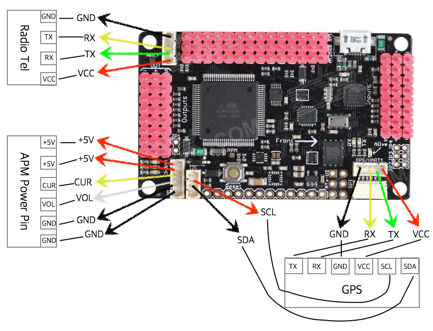
4. Next things are connect cables to GPS, Radio telemetry, 5V power cable for APM and then placed 3DR radio telemtry. Here is the connection diagram of APM power module, radio telemetry and external GPS to APM 2.6.
APM external HW connection

Here is the actual shot of those connections.
IMG_3772

5. After brain and heart were installed, now is time to attach the BL motor onto the ARM. IMG_3773

These motor assembly would be connected to aluminum pipe, which there is hole so that power cable of motor can be passed into this. IMG_3774

This is very easy even my son can do this. IMG_3776

Here is the result of motors, arm and center bar assembling. This is H frame, but the length of X and Y axis between motors are perfectly square. So this can be configured as X type frame in Mission Planner. square

6. Next is soldering 4 ESCs and APM power module onto the PCB board. And then attached these under the board using cable tie. How to solder 4 ESCs and power module? Please, refer to my previous post at this link: – How to solder 4 ESCs and power module onto PCB board. IMG_3777

7. Next is almost final that are connecting motor to eESCs, ESC to output pins of APM and radio receiver to input pins of APM. I introduced details about this step at my previous post at this link: – Quadcopter assembling IMG_3779

8. Final things are attaching back upper shell, attaching GPS module and put the propellers onto each motor. venture-assemble

All of parts are hided into the shell and looks very clean. IMG_3780

Quanum Venture frame kit review

While googling, I found out nice looking quadcopter frame kit named Quanum Venture. This is quad, 430mm wheel base and H type frame. As you know, most DIY drones are not beautiful, because every parts and wires are opened and look like all messed up. This frame kit has shell so that every parts can be hided into the body.

I ordered this at hobbyking.com and delivered in a week. The kit was well packed and here is the box.
IMG_3747

The reference picture on the box looks very good like cat fish. Here is the picture of unboxing.
IMG_3748

All frame parts were well safety packed and seem like very easy to assemble. Here is the picture of all components of this.
IMG_3750

There is two arms which is holed lightweight aluminum so that wires of from motor can be hided into this. upper cover is very soft- thin plastic. It also contains PCB board to connect ESC and Power cables, which it made me save the money to purchase additional power distribution board. With this, I’m ready to build up my 5th Quadcopter. I also prepared main parts.
IMG_3766

Here are the parts list what I prepared.
1. Frame kit : Quanum Venture
2. Motor : DYS BL 2212-920KV motor * 4 (with self locking cap)
3. ESC : Emax simonK 30A ESC *4 (I really appreciate to Mr. Hwang who sponsored me this)
4. Flight controller : APM 2.6
5. GPS : Ublox NEO-6M (55*55 size)
6. Radio telemetry : 3DR compatible 433Mhz kit
7. Radio receiver : Walkera 7CH receiver
8. Propeller : DJI style 9045 propeller
9. etc : wires, T plugs, 3mm gold bullet banana connectors and LEDs

Making simple, affordable micro quad

Drone for leisure has been exponentially popular at recent. When I been to airfield near my house at last year, there  just a few enthusiasts played their aero vehicles. But I can see lots of peoples fly their aerial vehicles at there. It’s understandable why DJI has became a billionaire.

Yeah, it’s really fun fly a drone. But, what are you gonna do when there is heavy rains or strong windy at outside? I strongly give you advice do not fly a drone under strong windy day. I had sad experienced that one of my drone flied away by this. She didn’t has enough power against to head wind. So just a think popup that make a tiny, simple and affordable quad to play indoor. And this would be very useful for training purpose. I shopped nice looking frame, brushed motor and receiver board. Here are the part lists.

  1. Body shell : Hubsan 107D —- $3.6
  2. 8mm hollow cup motor *4 —- $12
  3. QR ladybird receiver board —- $21
  4. Propeller set for micro quad —- $1.2
  5. Total —– $ 37.8

IMG_3657

This is Wakera’s QR lady bird receiver board compatible to my Devo 7 transmitter.
IMG_3661

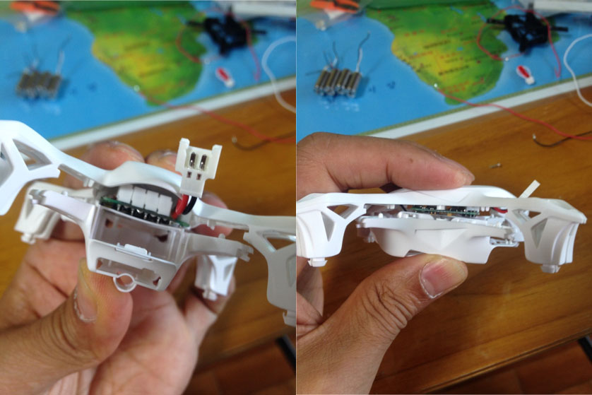
I placed the board into the body shell. It seemed nice fit to that. But screw hole needed to be removed.
IMG_3658

There was gab between upper and under shell. So the pin connectors also needed to be removed.
reciever does not fit

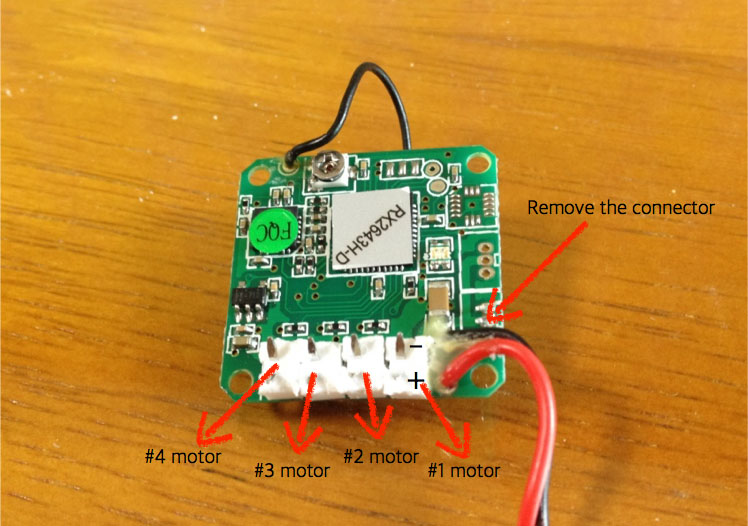
I cut off pin connectors and bent the pins. I refered QR ladybird’s manual to check the number of motors.
cutted receiver

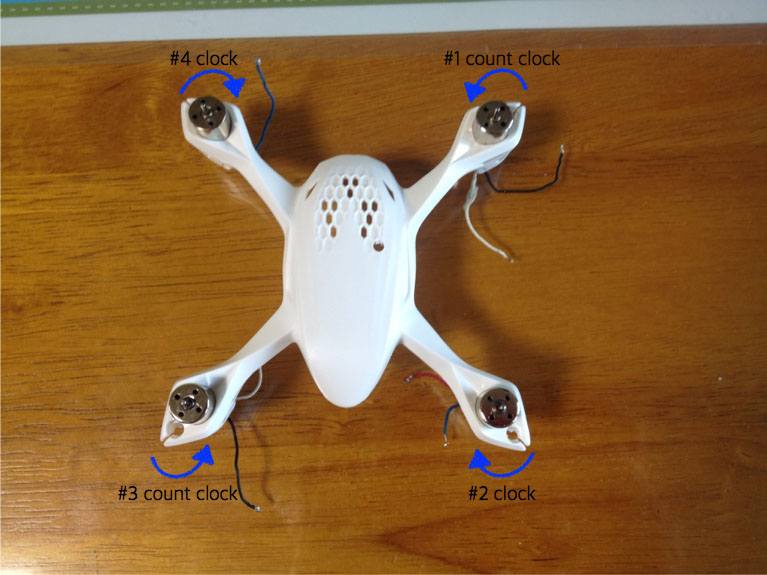
I placed motors into each mounting hole of the upper body shell’s arm according to rotate direction.
motor direction

After checked the # of motors and rotate direction, I soldered wires onto connector pins of the receiver board.
wire soldering

And I connected these wires to each motor.
IMG_3680

These mess wires were needed to be arranged like this.
IMG_3681

Finally, attached under body shell and propellers. Here was the result.
IMG_3688

I made two of this. 😉
IMG_3689

Okay. It was simple job and just only two hours to be done. Real final job is, I think, lifting her up stably. Let’s show how she lift up what I expected.

She was so stable than what I expected. A few hours later, I went out airfield and lift off her. See below video:

Testing flight of Hexacopter

I’m back. It’s been about 4 month since my last posting. I had done assembling my hexacopter 4 month ago but I didn’t test flight.
Actually, I deadly would liked to do that. But I couldn’t cause by terrible traffic accident and I had surgery operation on my neck spine.
I couldn’t move my neck by this for 4 month. Now I’m almost recovered. Thanks to my God.
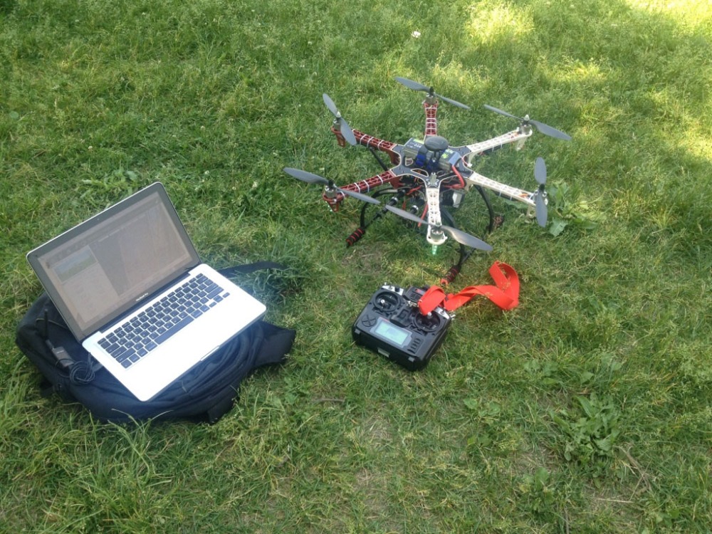
It was very drilled to had this testing flight as if it were my virgin flight.
hexa

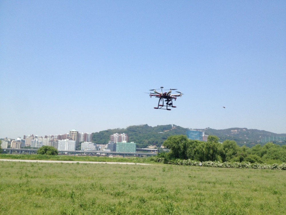
My special thanks to my second son who took good pictures and movies of this flight.
flight-hexa

Here is the video link of testing flight:

My overall feeling of hexacopter were that it is more stable than quad. But slower and need more battery capacity. With 5,200 mAH lipo battery, the flight time was around 15~18 minutes and 8~10 minutes with gimbal loading.
Well, I think I need serious consider to adopt 10,000 mAH lipo.

Drone upgrade to hexacopter

It’s been more than a month since my last posting. I spent hectic schedule to close my work in office, spent nice end of the year to meet good friends and skiing with my family.

My current Quadcopter seemed like had some burden to load gimbal, video transmitter and etcs. I tried to reduce the weight below 1.6KG. But it is overweighted to 1.8KG. So I decided to upgrade this to hexacopter.

There are some pros and cons of this compare to quadcopter.
Pros are:
1. Greater power and speed.
2. More safety due to additional two motors. If one motor is failed, this still can fly.
3. Higher payload.
4. Better efficient of motor load, because payload is distributed to two more motors.
Cons are:
1. Higher pricing
2. More difficult to carry due to larger size

Here are my new purchasing part list for this.
1. Diatone H550 Hex frame
2. Emax Simonk 30A ESC x 6EA
3. Tarot 2214/920KV brushless motor x 6EA
4. Landing gear kit for F550
5. Flysky 9CH RC transmitter with 8CH receiver
6. Carbon Fiber 1045 propeller

In this upgrade, I also replaced RC transmitter from Devo 7 to Flysky. Devo 7 is not bad, but it’s range is around 300m. I need more long range transmitter where Flysky can cover around 1.6Km.

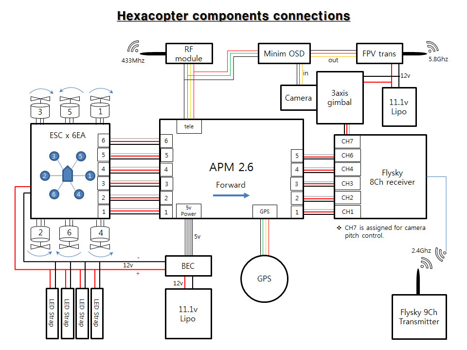
Here is block diagram of my building
apm-hexa

Flysky receiver is marked channel number instead of name of control.
In mode2, CH1 is roll, CH2 is pitch, CH3 is throttle and CH4 is yaw.
About RC transmitter setting of Flysky, I found out good posting from Diydrone forum. I refered this.

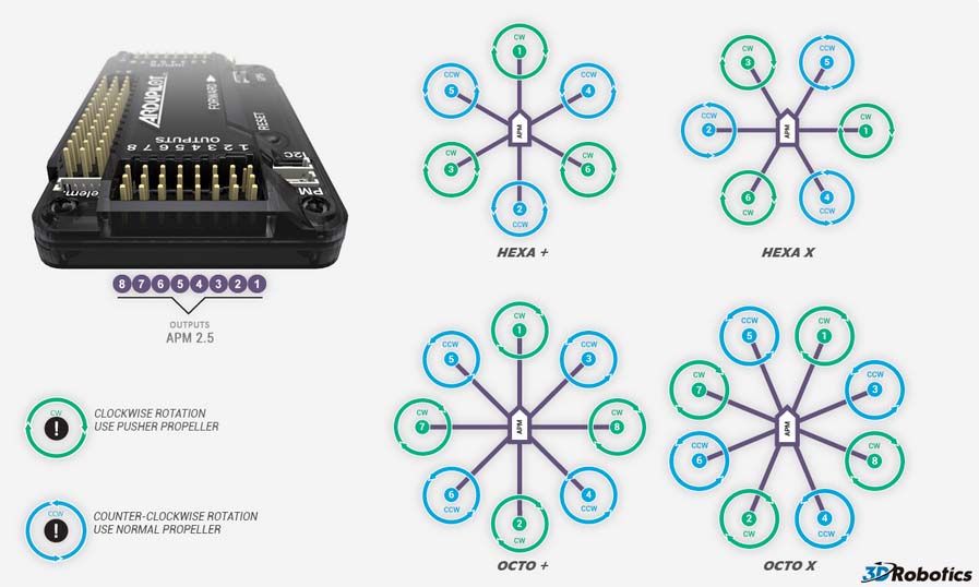
Motor sequence number of hexa is different to quad. Refer to below picture.
apm-hexa

Here are the parts.
IMG_3411

Additional pros of 550 size hexa has enough room to put in the PCB board.
IMG_3412

It took about 2 days to complete the assembly,flashing the Aurducopter3.2 firmware into APM and tunning.
IMG_3417

Here is the picture of result. Total gross weight is about 2.2KG including battery and gimbal with action camera. Too heavy….
IMG_3471

Drone crashing

Can we free from drone crashing?
I think it’s almost impossible to avoid from this.
I’m a experienced RC helicopter person. But I met theses badly crashing 4 times since I started this project. All crashes are related to autonomous flight like auto pilot, return to launch and loiter mode. Well tuned and proved commercial products also reported unintended crashing. Most of my cases are related to bad compass calibration. (Autonomous flight is totally defended on GPS.) So it is very important that master the manual control of drone before deploy the auto pilot.
Here is the video of crashing collection what I met:

Add on FPV(First person view) part 3 – Camera gimbal

Every drone used for aerial photography needs a gimbal. Why?
You will find out why this is needed when you see below video captured by camera mounted under drone without gimbal.

As you could see, there was shaky video caused by vibration from drone and also video wan’t stably fixed.
To resolve above issues, I should add on gimbal. Camera gimbal are used in stabilization systems designed to give the camera operator the independence of shooting without camera vibration or shake. Powered by two or three brushless motors, the gimbals have the ability to keep the camera level on all axes as the camera operator moves the camera. An IMU(internal measurement movement) responds to movement and utilizes its three separate motors to stabilize the camera.

Here are the components to build up 3-axis mini gimbal
1. Mini gimbal – DYS 3-axis gimbal for goPro
IMG_3309

2. Controller – Alexmos 8bit 3-axis gimbal controller
alexmos

Main board flash setting values and control roll and pitch movement.
alexmos main

I soldered power cable on the main board at first.
IMG_3312

Next step is attach the board under the gimbal mount board where I made a hole.
IMG_3313

And then, attach the yaw extension board onto the main board and connected wires.
IMG_3322

Final wiring is connect the IMU sensor.
IMG_3324

After assembling is completed, the most important thing should be set is calibrating the sensor.
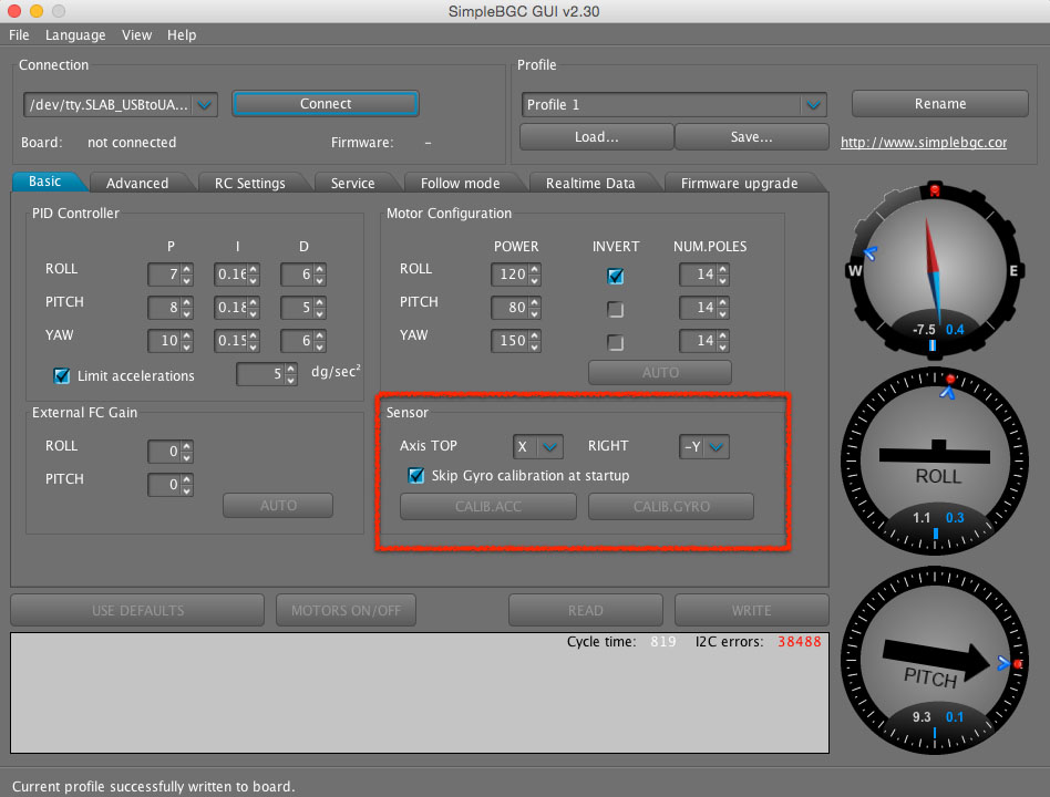
To calibrate this, download management software at here–>connect the controller to a computer via usb cable–>excute ‘CALIB.ACC’ menu.
Before perform this, It is very important that which direction is the IMU sensor replaced. IMU has three axis where are Z, X and Y. So Axis top and right direction should be defined. In my case, Axis top was positive X and right was negative Y.
IMU direction

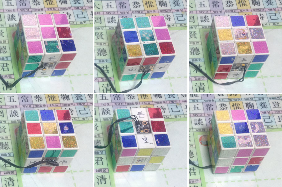
I attached the IMU sensor to a cube to fix the level and performed calibration. It took about 3 seconds and it’s very important do not move sensor during calibration.IMG_3353

It is highly recommended perform this 6 positions like below:
6 position calibration

After done this, I click the ‘WIRTE’ button to store the setting values and mounted under the drone.
IMG_3327

Gimbal seemed like work good when I tested. Please refer to below video link:

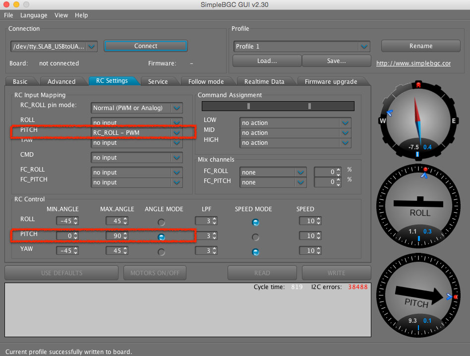
I explained what I experienced in a short and simply, but actually, I struggled this for a week. Finally, What I have done was set the pitch degree control using RC transmitter. I connected the RX_pitch connector to gear channel of RC receiver and set the parameters at manager software. camera pitch

Here is the result video what was worked:

I think I’m ready to take air video. And will take interesting scenes at this weekend.